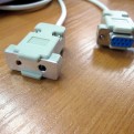
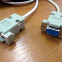
The image below is a link. Try to click on it.

Irdroid serial IR cable specifications and description

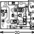
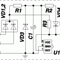
The irdroid serial cable Kit , is a inexpensive serial (RS-232) device that allows you to capture IR remotes data. The Serial cable kit does not have any decoding logic. All the infrared signal decoding is performed via the irrecord application , which is part of the LIRC project.  In the Gallery below the schematics, and the pcb layout files of the Irdroid serial IR cable kit are provided.

The following is required to build the kit:

  • Soldering Iron
  • FTP flexible cable or any other cable with 6 wires
  • DB9 RS-232 connector

The Kit contains the following components:

1.PCB  0217– 1 pcs.
2. U1

IR Receiver TSOP1838

SFH5110-38 or PNA4612M– 1 pcs.
3. VD1,2Diode double BAY70 SMD– 1 pcs.
4. VD3Zener diode 5,1V– 1 pcs.
5. VD4LED F3

– 1 pcs.

6. С1capacitor 22µF/6,3V– 1 pcs..
7. R1resistor 910 (820)Ω– 1 pcs.
8. R2resistor 1,8 (2,2)kΩ– 1 pcs.
9. R3resistor 4,7 (3,3)kΩ– 1 pcs.
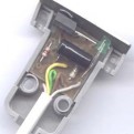
10.Enclosure Canon DB 9 / front plate– 1 pcs.

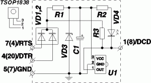
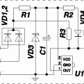
The Serial Ir receiver is to be connected to a unused RS-232 (serial) port of your computer and it is power supplied from the serial port. For this purpose the lines RTS and DTR are used. The Signal lines RTS and DTR are established in a level “0” state, this level (in the RS-232 standard) corresponds to a voltage of +10 volts. The Zener diode VD3 limits this voltage to 5 volts, which is needed for the proper function of the infrared receiver IC. The Capacitor C1 has a filtering function. The Infrared receiver module U1 is a specialized IC, which amplifies the infrared signals and demodulates them. The carrier frequency between 30 and 50khz (most commonly used 38khz) is used.  Depending on wheather there is a carrier frequency emitted or not, the output pin of U1 generates voltages which corespond to logical “0” and logical “1” . These bits are then transfered to the DCD line of the RS-232 and it is further decoded by the software installed in the PC. Most of the Software solutions that work with the infrared receiver module allows for choosing of the line which carries the data. In our case it is the DCD line.The cable lenght of the receiver should not be longer than 2 meters ( a limitation of the RS-232 ).

For information regarding the software used to capture IR codes please refer to this article:

https://irdroid.com/2013/02/recording-ir-remotes-using-inexpensive-ir-receiver-device/


You could purchase irdroid serial IR receiver from the DIY section below :

[print_thumbnail_slider]

The image below is a link. Try to click on it.

Building Irdroid v1.0 on a breadboard

The Irdroid v1.0 infrared aplifier module for Android , built from our schematics on a breadboard by  “7thrx”

Downloads:

[mailchimpsf_form]

The image below is a link. Try to click on it.

Recording IR remotes using inexpensive IR Receiver device

Many people asked me weather the Irdroid hardware modules support “learning” of infrared remote codes. The two modules (Irdroid v1.0 and Irdroid v2.0) have only IR transmit functionality for the moment. There are plenty of units available all over the Internet which offer the infrared codes recording functionality, they are compatible with LIRC , and can be purchased for relatively low cost depending on their features. Here I will present a very simple device that can be built in a minutes. It is a DCD Serial Device (RS-232 interface), it works with both LIRC (for linux) and Winlirc (for Windows). The device schematic consist of a quite few components and it is perfect for DIY fans.

Irdroid IR Receiver schematic

Irdroid IR Receiver schematic

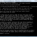
The schematic consist of a standard 38khz IR receiver module, 3 diodes, 1 LED indication LED and 3 resistors . The communicates with a PC is via a RS-232 serial interface and all the components are on a very small PCB inside a standard DB-9 female serial connector. I  will not explain here how the hardware and / or software works. There are already plenty of explanations of the above schematic all over the Internet. The schematic is shown in order to demonstrate the simplicity of the device. I will focus on using the Device with winlirc as it is most commonly used with Windows and I am using it as well. Winlirc is responsible for processing the signals received by the device and it can also send signals to the device, so it is a transceiver module. The application “irrecord.exe” (part of the winlirc package) under windows is used to capture the infrared remote codes. The application “reads” the received signal from the serial port (in our case) and it tries to decode and store the signal into a file. Before using “irrecord” you need to choose the driver for a DCD serial device from winlirc configuration settings and select the serial port to which the device is attached to. Irrecord will try to identify the protocol of the received infrared signal and to decode it and store it in a LIRC configuration file, or if it is unknown protocol it can store the RAW codes in the file, so that they can be reproduced later. Irrecord is a command-line tool and you will need to type some command line  parameters as well in order to capture your remote codes.  

The IR receiver hardware works with a standard computer serial ports, it won’t work on a USB to RS-232 cables as these are not emulating the serial port with all its signal lines. For best result use a desktop PC with available free serial port in order to connect the IR receiver.

If you want to get a IR receiver module the cost is $12 and you can buy one from the Irdroid DIY Section.

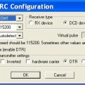
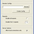
The screenshots shows the winlirc configuration settings dialogue and the Irdroid IR receiver unit / schematic . From this dialogue you need to select the SerialDevice.dll driver for the Serial IR receiver. Then you need to click on driver setup in order to set the needed configuration settings foe the Serial IR Receiver. The screenshot shown on the right shows you the SerialReceiver driver configuration settings. You need to select the serial port number to which the device is attached. The baudrate is 115200 in most cases and you need to select DCD Receiver type as the Serial IR Receiver is a DCD type device.

Continue reading