-
-
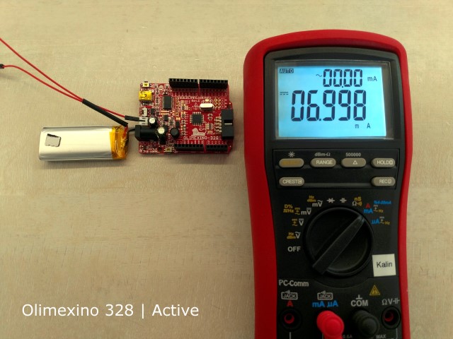
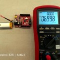
Olimexino 328 power consumption active
-

-
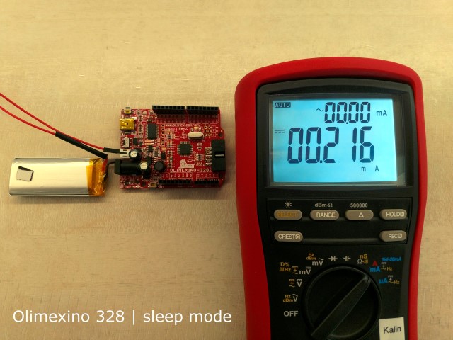
Olimexino 328 power consumption sleep mode
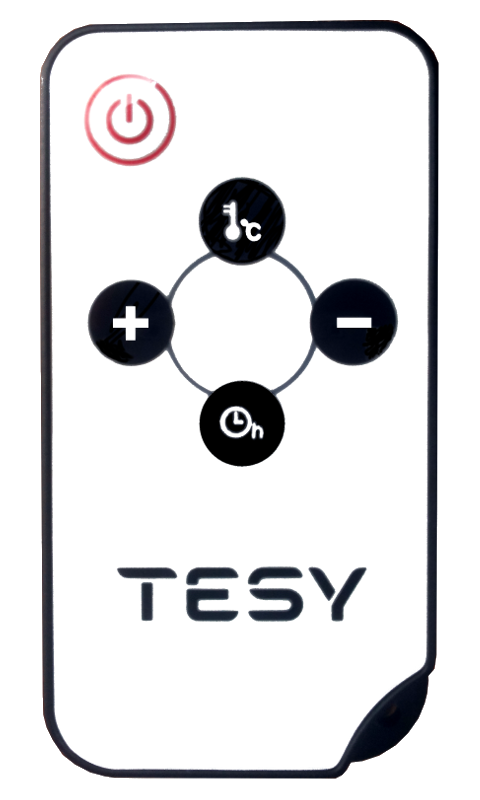
Designing battery powered devices that have to run for years on batteries is a challenge. If you look around you will see that most of the home appliances such as TVs, Music devices, Aircons, Heaters, Fans and so on are controlled using battery powered remote controls. The remote controls used with these devices should run for long periods of time on batteries.
How is this achieved? Can we design a embedded custom remote control, by using open source hardware and software tools?
The Answer is Yes. We can use off-the-shelf low energy power consumption microcontrollers which will allow us to run on batteries for long periods of time. In this post we will review the possibilities with Atmel Atmega328P microcontroller, running at 16MHz and powered by 3.3V. We will also review and measure some off-the-shelf open source hardware development boards like Arduino, Olimexino etc.
We will review the following:
According to the MCU specification the microcontroller supports sleep modes with minimal power consumption (Approximately 0.1uA).
For the measurements we will use the BRYMEN 867s Digital Multimeter.
According to the MCU Specification we will have to power the Atmega with 3.3V in order to benefit from the lower current/power consumption. For the breadboarded version,we have just the Microcontroller, a quartz and two caps we are expecting to get the lowest result/ measurement.
In terms of software for our tests we will use a test program that will put the MCU in sleep mode, written for Arduino . The test program does really a simple thing – when the MCU is awaken / not in sleep mode it flashes the board LEDs for 5 times it waits for 10 seconds, then the microcontroller is forced to enter sleep mode. The sleep mode can be interrupted by grounding the INT0 pin of the MCU. The idea is that when in sleep mode all MCU peripheral and core is switched off and therefore we have minimal power consumption. Nothing is running in sleep mode, except for the logic that wakes up the MCU. The main program of the MCU is executed every time waken up, it does its thing and then it goes to sleep after a user defined period of time (usually several seconds after it performs a task.)
We have the following listing:
/*———————————————————————-*
* Sleep demo for ATmega328P. *
* Wire a button from digital pin 2 (INT0) to ground. *
* Wire an LED with an appropriate dropping resistor from pin D13 to *
* ground. *
* Pushing the button wakes the MCU. *
* After waking, the MCU flashes the LED, then waits 10 seconds before *
* going back to sleep. *
* *
* Jack Christensen 07May2013 *
* *
* Tested with Arduino 1.0.5 and an Arduino Uno. *
* Test conditions for all results below: *
* 5V regulated power supply, fed to the Vin pin *
* 16MHz system clock *
* Fuse bytes (L/H/E): 0xFF / 0xDE / 0x05 *
* Optiboot bootloader *
* *
* Uno R1 *
* 38mA active, 26mA with MCU in power-down mode. *
* *
* Uno SMD edition *
* 42mA active, 31mA power-down. *
* *
* Adafruit Boarduino *
* Power select jumper set to “USB”, USB (FTDI) not connected. *
* 15mA active, 3mA power-down. *
* *
* Adafruit Boarduino without power LED *
* 12mA active, 0.1µA power-down. *
* *
* Breadboarded ATmega328P-PU *
* 12mA active, 0.1µA power-down. *
* *
* This work is licensed under the Creative Commons Attribution- *
* ShareAlike 3.0 Unported License. To view a copy of this license, *
* visit http://creativecommons.org/licenses/by-sa/3.0/ or send a *
* letter to Creative Commons, 171 Second Street, Suite 300, *
* San Francisco, California, 94105, USA. *
*———————————————————————-*/
#include <avr/sleep.h>
const int LED = 13; //LED on pin 13
const unsigned long KEEP_RUNNING = 10000; //milliseconds
void setup(void)
{
//to minimize power consumption while sleeping, output pins must not source
//or sink any current. input pins must have a defined level; a good way to
//ensure this is to enable the internal pullup resistors.
for (byte i=0; i<20; i++) { //make all pins inputs with pullups enabled
pinMode(i, INPUT_PULLUP);
}
pinMode(LED, OUTPUT); //make the led pin an output
digitalWrite(LED, LOW); //drive it low so it doesn’t source current
}
void loop(void)
{
for (byte i=0; i<5; i++) { //flash the LED
digitalWrite(LED, HIGH);
delay(100);
digitalWrite(LED, LOW);
delay(100);
}
delay(KEEP_RUNNING); //opportunity to measure active supply current
digitalWrite(LED, HIGH); //one blink before sleeping
delay(100);
digitalWrite(LED, LOW);
goToSleep();
}
void goToSleep(void)
{
byte adcsra = ADCSRA; //save the ADC Control and Status Register A
ADCSRA = 0; //disable the ADC
EICRA = _BV(ISC01); //configure INT0 to trigger on falling edge
EIMSK = _BV(INT0); //enable INT0
set_sleep_mode(SLEEP_MODE_PWR_DOWN);
cli(); //stop interrupts to ensure the BOD timed sequence executes as required
sleep_enable();
//disable brown-out detection while sleeping (20-25µA)
uint8_t mcucr1 = MCUCR | _BV(BODS) | _BV(BODSE);
uint8_t mcucr2 = mcucr1 & ~_BV(BODSE);
MCUCR = mcucr1;
MCUCR = mcucr2;
//sleep_bod_disable(); //for AVR-GCC 4.3.3 and later, this is equivalent to the previous 4 lines of code
sei(); //ensure interrupts enabled so we can wake up again
sleep_cpu(); //go to sleep
sleep_disable(); //wake up here
ADCSRA = adcsra; //restore ADCSRA
}
//external interrupt 0 wakes the MCU
ISR(INT0_vect)
{
EIMSK = 0; //disable external interrupts (only need one to wake up)
}
The code will flash the board leds 5 times, wait for 10 seconds, to allow us to make a measurement and then it will force the MCU to enter sleep mode.
We have tested breadboarded Atmega328, Arduino UNO R3 and Olimexino 328, as you can see from the code header, other people has tested and mesured also for other boards , based on Atmega328.
The results for the breadboarded Atmega328 are stunning – 0.1uA in sleep mode, though there is nothing else than the microcontroller, a quartz and 2 caps,powered by 3.3V. (the first pretendent )
The second in this list is the Olimexino 328 , running at 16MHz, powered by 3.3V. The board is designed with on board charger for connecting external batteries. In a running mode the total power consumption at 3.3V was about 7ma , in sleep mode this board consumes approximately 200uA, which makes it usable for battery powered devices. (Our second pretendent)
And finally the Arduino UNO R3 gave us high power consumption both active and sleep modes ( 38mA active, 26mA with MCU in power-down mode ) which renders it unusable for designing battery powered infrared applications.
Conclusion:
The user should either make a custom design , using the Atmega328 and create a design with low energy consumption in mind, or use the Olimexino 328 as a basis, which is open source hardware and it has a decent power consumption both active and sleep modes.
Downloads: