The Car Halo LED Light controller is controlled using a cheap remote control using a EV1527 Encoder chip, which is compatible with the Arduino / Raspberry Pi rc-switch library. I has able to clone the remote control buttons using a cheap RF radio transmitter and receiver AM modules, working at 433MHz. Then I was able to control the Car Halo Light led controller , using the Irdroid IoT SmartHub.
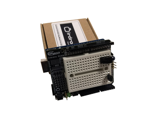
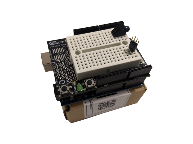
The latest gadget in our online store is the Infrared (IR) Proto Shield for Arduino. It can be used to prototype and experiment with Infrared on Arduino. The board comes with a High Power IR LED, High Quality IR Receiver IC , SMD and BreadBoard prototyping area.
In some cases, the automatic “update db” option will download automatically the default licd.conf file that ships with the Irdroid v.0.4 app, but it will not parse it in the UI. In this case you can use a “File Manager” application like this one to locate the downloaded database file. It should be downloaded and stored in your internal SD Card under the /sdcard/tmp/ folder. Locate the file named “t.conf” and copy it to your external SDcard under /tmp folder (create /tmp folder if it doesn’t exist) . Using the file manager tap on additional info when the t.conf file is selected and write down the full file path shown in the “additional info” (you will need it later in the Irdroid v.0.4 app) . Start the Irdroid app and select “Parse File” and enter the exact path to the “t.conf” file. Once done, the default remote brands will show up in the list of devices.
In this Blog post I am just re-blogging / sharing our Blog post from our EU website https://irdroid.eu about Irdroino Infrared Shield for Arduino. You can read the whole Blog post and watch a demo vide by following the link below:
Irdroid started as a Hobby Project, founded by Georgi Bakalski back in 2011. Today the Hobby project transformed into a Innovative and Successful Company (Hardware Group Ltd.). We believe in the open source initiative and we started the project as a open source hardware and open source software. During the years we have developed, devices and software for GNU Linux, MS Windows, Mac OS X, Arduino and more. We believe that learning by sharing is a key for the progress. Today Irdroid is a registered trademark of Hardware Group Ltd Bulgaria and it provides open source hardware and open source software devices and software development services for Google Android, GNU Linux , Windows and Mac OS X . Our Devices and services help hundreds of individuals and StartUp Companies around the world to bootstrap their new products and ideas.
We would like to thank all our Customers during the years, they are the one’s that kept the project up and provided precious feedback for improving it.
The latest arrival in our online store – https://www.irdroid.eu is the USB OTG Infrared Adapter for Android. It allows you to control all your home appliances, that are controlled via Infrared Remotes. It has a Infrared Transmitter and infrared receiver and it has infrared “learning” functionality. The unit is compatible with ZaZa Remote App.
You can read more about the product by following the link below:
The WiFi to Infrared (IR) converter module will allow you to remotely control your home appliances ( Air Conditioners, TVs , Audio, STBs, DIY devices and many more ), using you smartphone via the free application for Android and iOS. The module comes with a microUSB power supply cable and a user manual for downloading and configuring the application for Android and iOS. The unit is truly universal as you can choose thousands of devices remote control codes and in addition if your target device is not in the database, you can “record” your remote control as the wifi to infrared module has a infrared “learning” function, so that you seamlessly add your device in case it is not in the database of supported devices.
The video below shows unboxing of the WiFi to Inrared module
The Wifi to Infrared module has build in functions for automatically recognizing the target device / infrared remote control . If you have the original device remote control you can add it by simply scanning the original remote control infrared commands. These scanning / learning functions are build in in the free applications for Android and iOS that comes with the WiFi to Infrared module.
The video below demonstrates how the remote control “learning” procedure works. It shows you how to add an Air Conditioner remote control in the App.
You can purchase WiFi to Infrared module from the link below:
Designing battery powered devices that have to run for years on batteries is a challenge. If you look around you will see that most of the home appliances such as TVs, Music devices, Aircons, Heaters, Fans and so on are controlled using battery powered remote controls. The remote controls used with these devices should run for long periods of time on batteries.
How is this achieved? Can we design a embedded custom remote control, by using open source hardware and software tools?
The Answer is Yes. We can use off-the-shelf low energy power consumption microcontrollers which will allow us to run on batteries for long periods of time. In this post we will review the possibilities with Atmel Atmega328P microcontroller, running at 16MHz and powered by 3.3V. We will also review and measure some off-the-shelf open source hardware development boards like Arduino, Olimexino etc.
According to the MCU specification the microcontroller supports sleep modes with minimal power consumption (Approximately 0.1uA).
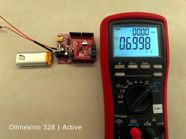
For the measurements we will use the BRYMEN 867s Digital Multimeter.
According to the MCU Specification we will have to power the Atmega with 3.3V in order to benefit from the lower current/power consumption. For the breadboarded version,we have just the Microcontroller, a quartz and two caps we are expecting to get the lowest result/ measurement.
In terms of software for our tests we will use a test program that will put the MCU in sleep mode, written for Arduino . The test program does really a simple thing – when the MCU is awaken / not in sleep mode it flashes the board LEDs for 5 times it waits for 10 seconds, then the microcontroller is forced to enter sleep mode. The sleep mode can be interrupted by grounding the INT0 pin of the MCU. The idea is that when in sleep mode all MCU peripheral and core is switched off and therefore we have minimal power consumption. Nothing is running in sleep mode, except for the logic that wakes up the MCU. The main program of the MCU is executed every time waken up, it does its thing and then it goes to sleep after a user defined period of time (usually several seconds after it performs a task.)
We have the following listing:
/*———————————————————————-*
* Sleep demo for ATmega328P. *
* Wire a button from digital pin 2 (INT0) to ground. *
* Wire an LED with an appropriate dropping resistor from pin D13 to *
* ground. *
* Pushing the button wakes the MCU. *
* After waking, the MCU flashes the LED, then waits 10 seconds before *
* going back to sleep. *
* *
* Jack Christensen 07May2013 *
* *
* Tested with Arduino 1.0.5 and an Arduino Uno. *
* Test conditions for all results below: *
* 5V regulated power supply, fed to the Vin pin *
* 16MHz system clock *
* Fuse bytes (L/H/E): 0xFF / 0xDE / 0x05 *
* Optiboot bootloader *
* *
* Uno R1 *
* 38mA active, 26mA with MCU in power-down mode. *
* *
* Uno SMD edition *
* 42mA active, 31mA power-down. *
* *
* Adafruit Boarduino *
* Power select jumper set to “USB”, USB (FTDI) not connected. *
* 15mA active, 3mA power-down. *
* *
* Adafruit Boarduino without power LED *
* 12mA active, 0.1µA power-down. *
* *
* Breadboarded ATmega328P-PU *
* 12mA active, 0.1µA power-down. *
* *
* This work is licensed under the Creative Commons Attribution- *
* ShareAlike 3.0 Unported License. To view a copy of this license, *
* visit http://creativecommons.org/licenses/by-sa/3.0/ or send a *
* letter to Creative Commons, 171 Second Street, Suite 300, *
* San Francisco, California, 94105, USA. *
*———————————————————————-*/
#include <avr/sleep.h>
const int LED = 13; //LED on pin 13
const unsigned long KEEP_RUNNING = 10000; //milliseconds
void setup(void)
{
//to minimize power consumption while sleeping, output pins must not source
//or sink any current. input pins must have a defined level; a good way to
//ensure this is to enable the internal pullup resistors.
for (byte i=0; i<20; i++) { //make all pins inputs with pullups enabled
pinMode(i, INPUT_PULLUP);
}
pinMode(LED, OUTPUT); //make the led pin an output
digitalWrite(LED, LOW); //drive it low so it doesn’t source current
}
void loop(void)
{
for (byte i=0; i<5; i++) { //flash the LED
digitalWrite(LED, HIGH);
delay(100);
digitalWrite(LED, LOW);
delay(100);
}
delay(KEEP_RUNNING); //opportunity to measure active supply current
digitalWrite(LED, HIGH); //one blink before sleeping
delay(100);
digitalWrite(LED, LOW);
goToSleep();
}
void goToSleep(void)
{
byte adcsra = ADCSRA; //save the ADC Control and Status Register A
ADCSRA = 0; //disable the ADC
EICRA = _BV(ISC01); //configure INT0 to trigger on falling edge
EIMSK = _BV(INT0); //enable INT0
set_sleep_mode(SLEEP_MODE_PWR_DOWN);
cli(); //stop interrupts to ensure the BOD timed sequence executes as required
sleep_enable();
//disable brown-out detection while sleeping (20-25µA)
uint8_t mcucr1 = MCUCR | _BV(BODS) | _BV(BODSE);
uint8_t mcucr2 = mcucr1 & ~_BV(BODSE);
MCUCR = mcucr1;
MCUCR = mcucr2;
//sleep_bod_disable(); //for AVR-GCC 4.3.3 and later, this is equivalent to the previous 4 lines of code
sei(); //ensure interrupts enabled so we can wake up again
sleep_cpu(); //go to sleep
sleep_disable(); //wake up here
ADCSRA = adcsra; //restore ADCSRA
}
//external interrupt 0 wakes the MCU
ISR(INT0_vect)
{
EIMSK = 0; //disable external interrupts (only need one to wake up)
}
The code will flash the board leds 5 times, wait for 10 seconds, to allow us to make a measurement and then it will force the MCU to enter sleep mode.
We have tested breadboarded Atmega328, Arduino UNO R3 and Olimexino 328, as you can see from the code header, other people has tested and mesured also for other boards , based on Atmega328.
The results for the breadboarded Atmega328 are stunning – 0.1uA in sleep mode, though there is nothing else than the microcontroller, a quartz and 2 caps,powered by 3.3V. (the first pretendent )
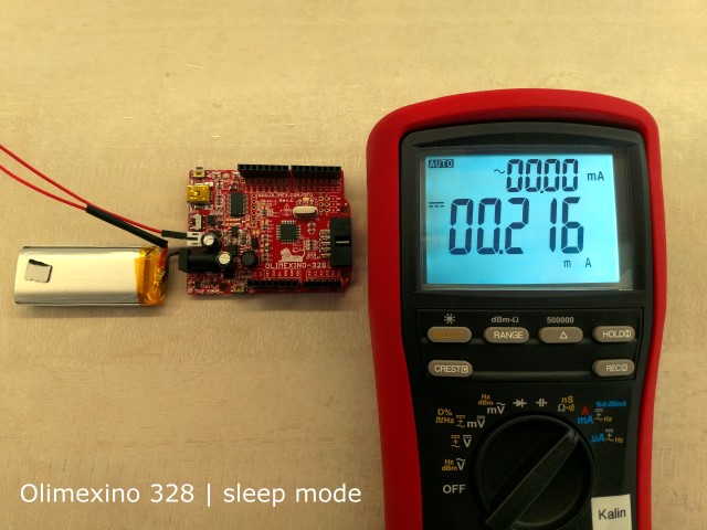
The second in this list is the Olimexino 328 , running at 16MHz, powered by 3.3V. The board is designed with on board charger for connecting external batteries. In a running mode the total power consumption at 3.3V was about 7ma , in sleep mode this board consumes approximately 200uA, which makes it usable for battery powered devices. (Our second pretendent)
And finally the Arduino UNO R3 gave us high power consumption both active and sleep modes ( 38mA active, 26mA with MCU in power-down mode ) which renders it unusable for designing battery powered infrared applications.
Conclusion:
The user should either make a custom design , using the Atmega328 and create a design with low energy consumption in mind, or use the Olimexino 328 as a basis, which is open source hardware and it has a decent power consumption both active and sleep modes.
We got a nice email from a customer from the Irdroid community saying that the Irdroid USB Infrared Transceiver works without any drivers on Windows 10. He tested Also with Windows Server 2012 and there was a driver issue , using the drivers we provide from the download section. The Issue with Windows 8 and Windows Server 2012 is that signed USB ACM drivers are needed. Windows Server 2012 requires that all drivers need to be signed, The USB Infrared Transceiver can work with Windows 8 but the workaround is that you need to turn off the signed driver requirement.
You can deactivate the forcing of signed drivers by using following Settings. Open a Command Prompt (cmd) as Administrator and type in following two commands. bcdedit -set loadoptions DISABLE_INTEGRITY_CHECKS bcdedit -set TESTSIGNING ON With bcdedit you´re configurating the bootmenu of windows, so be careful. If something goes wrong you´ll need a windows dvd to repair the bootmanager. After a restart you can install the driver normally. You just have to confirm to install the unsigned driver, just like in older versions of Windows.
This year’s (2017) TuxCon open source Linux conference took place in Plovdiv, Bulgaria. On the second day of this gathering ( the Workshop day) we all got a free and open source soldering Kit – the TuxCon Kitty conference badge (Thank you Olimex). The kit included a Atmel Attiny85 microcontroller, the TuxCon kitty pcb a buzzer two leds (the Kitty eye’s) one battery, battery holder and several resistors, capacitors and diodes.
I was on the conference with my son and we had a lot of fun assembling the kits. The kid was really exited to make his own toy and play with the other kids, attending the conference. Weeks after the conference I found the TuxCon kitty badge in my drawer and decide to make something cool with the Kitty badge – To turn it into a TuxCon Kitty TV BGone Mod Irdroid – To make it possible to switch ON/OFF any television by simply replacing several components from the existing design. The software that I have used simply sends a bunch of TV Power (ON/OFF) infrared commands in a loop.
Hardware Mod:
Remove / desolder R1,R2, R3 and R4
Solder 22 Ohm 0805 resistor to R1
Remove Led1 and solder IR LED (TSAL6200)
Desolder D1 and solder a micro switch/button in its place
Software:
The TuxCon Kitty badge is compatible with Arduino and comes pre-programmed with a bootloader and default code. I have programmed a new TuxCon Kitty BGone firmware using a STK500 programmer and desoldering/soldering the MCU (I havent yet found a way to write HEX using the Arduino IDE / the default bootloader in ATTiny85 that shipped with the badge) . I have used a Tiny85 code by Mitch Altman + Limor Fried (Adafruit Industries)

")